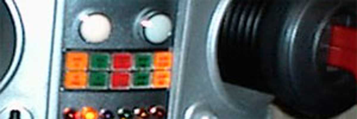
 You have to start somewhere so I decided to start by building the B9 Brain. The brain is the triangle section that sits inside the clear plastic bubble. It is also where “eyes” reside. The eyes are considered the two clear ovals at the far right and left sides of the front of the brain. So, it just makes sense to start the building process here.
I cut the brain side panels out of sheet styrene. The frame is made out of Clear Acrylic. Acrylic is really great to work with. You can cut it, drill it and even tap threads into it. Here I have about 12 lights installed. The local Radio Schwack ran out of sockets so I’ll have to hit up another one in town soon.
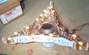 Well, I had to visit 3 stores to find enough lamp sockets. There are 22 lamps inside the brain and 3 that stick out the top. I tried to take a picture with all the lamps on but some started blinking immediately. Also, two bulbs were duds.
I took all the lights and sockets out so that I could glue the side panels on. I filled several uneven spots (caused by the adhesive softening the styrene from the back). It’s about ready to be painted. I still need to come up with some lenses.
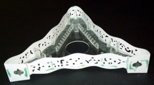 I painted my Brain tonight. I used Dupli-Color T177 Gunmetal. It came out pretty good. Re-installed all the light sockets and put back in the blinking bulbs (type 258). I hooked everything up to a 12 V dc power supply and cranked it up. Still no lenses for the “eyes”.
  I think I’ll dissect a few “one-time use” cameras. I have several lying around here.
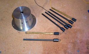 I made my own light rods from 1/4 brass tubing. A screw type lamp socked was soldered onto a 5 inch length of tubing.
I made the mold from two pieces of clear acrylic. I clamped them together and drilled a 1/4 inch hole down the center for the rod to pass through. I then used a larger drill and drilled down about an inch. This creates the cavity for the lamp socket. The mold is coated with a mold-release and it is allowed to dry before casting the part. Be sure to check out my New Silicone Rubber Mold Making How-to Guide.
The light rods are molded from Castomold-FP, a flexible molding plastic made by Castolite. Here’s one of the rods being molded. The wood dowel sticking out the top was screwed into the lamp socket and coated with mold release to prevent the plastic from sticking to it. Here’s the light rod assembled and painted. I think they came out great.
The Brain Cone is made out of machined aluminum. I plan on motorizing the light rods so that they will oscillate up and down. To hold the light rods in place and allow them to pivot, I put a groove around the inside of the brain cup dead center through the seven openings. A piece of piano wire will be strung through each of the light rods. I then filled up the cup (while upside-down) with plastic resin to just under the rod holes.
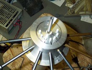 I drilled seven holes down through the top of the cup, and through the plastic resin. These holes are for the push rods that will raise and lower the light rods. Here you see the seven rods in place, as well as the center shaft that the crown will be attached to.
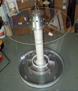 FINALLY! I took a big step and drilled the mounting holes in my bubble and bubble plate. Well, actually, I didn’t drill the holes but rather melted them in. I started by drilling the first hole in the bottom plate and CRACK. It didn’t go well. Just as I feared. This was why I put off drilling it for over a year. But I was fortunate to have it in a spot that does not show because it is under the center brain cone. Not wanting to repeat the mistake for the holes that show, I used my soldering iron to melt the holes in the plate as well as the bubble. I then used a Dremel tool to round out and smooth the holes. It went pretty well.
I used plastic screws and inserts to connect the bubble to the bottom plate. While not the same method as the original, I figured the less metal screwing into the plastic bubble, the better.
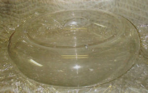 Here’s my bubble (upside down) on my well-padded workbench. As you can see, the clear plastic screws blend in quite well. Tomorrow I hope to test fit the brain into the bubble.
